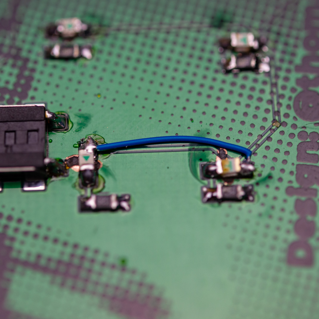
There are a few things that are a little tricky with the assembly of the 35c3 badge, since I have decided to use some of the components slightly outside their intended usecase. There are also a few things to be careful with, because I made a design error and had to rework the PCBs with a rotary tool to remove some copper that was in the wrong place (specifically where the light need to shine through the PCB).
The design files on Github has the error fixed. What I had forgotten was to make keepout areas under each LED, so that the ground fill wouldn’t flow in under the components.
Tools needed
To assemble this kit, there are a few tools that you will need. If you have already done electronics, you probably have these, but if you are onsite at 35c3 in Leipzig, you will probably be able to use the tools in the hardware hacking area, if you politely asks the people there, there might even be some friendly folks that can help out if stuff isn’t working.
- Soldering iron (preferably with a somewhat small tip, but you don’t need a super thin one, that will just have difficulty transfering heat to the pads)
- Solder
- Tweezers (to hold the small SMD components)
- Heavy duty side cutter (to cut the leads on the battery holder, the small ones normally used for electronics will be ruined due to the spring steel used for the leads)
- Multimeter (to check for short circuits/continuity)
- 2x AA batteries (to power the badge)
Good practice
Since the areas, that have been reworked to remove some copper, will have small areas of copper exposed, which are connected to ground, it’s very easy to accidentally connect these to VCC, and effectively create a short circuit. When assembling the board, it is recommeded that you frequently check that there are no short circuits, primarily between VCC and GND. If you solder on the power switch early, and turn the board on (switch lever position down towards the battery), it’s easy to check between the large round pad on the coin cell holder (GND) and one of the rectangular ones next to it (VCC). If you use the continuity test with audible feedback on the multimeter, this is a very quick test.
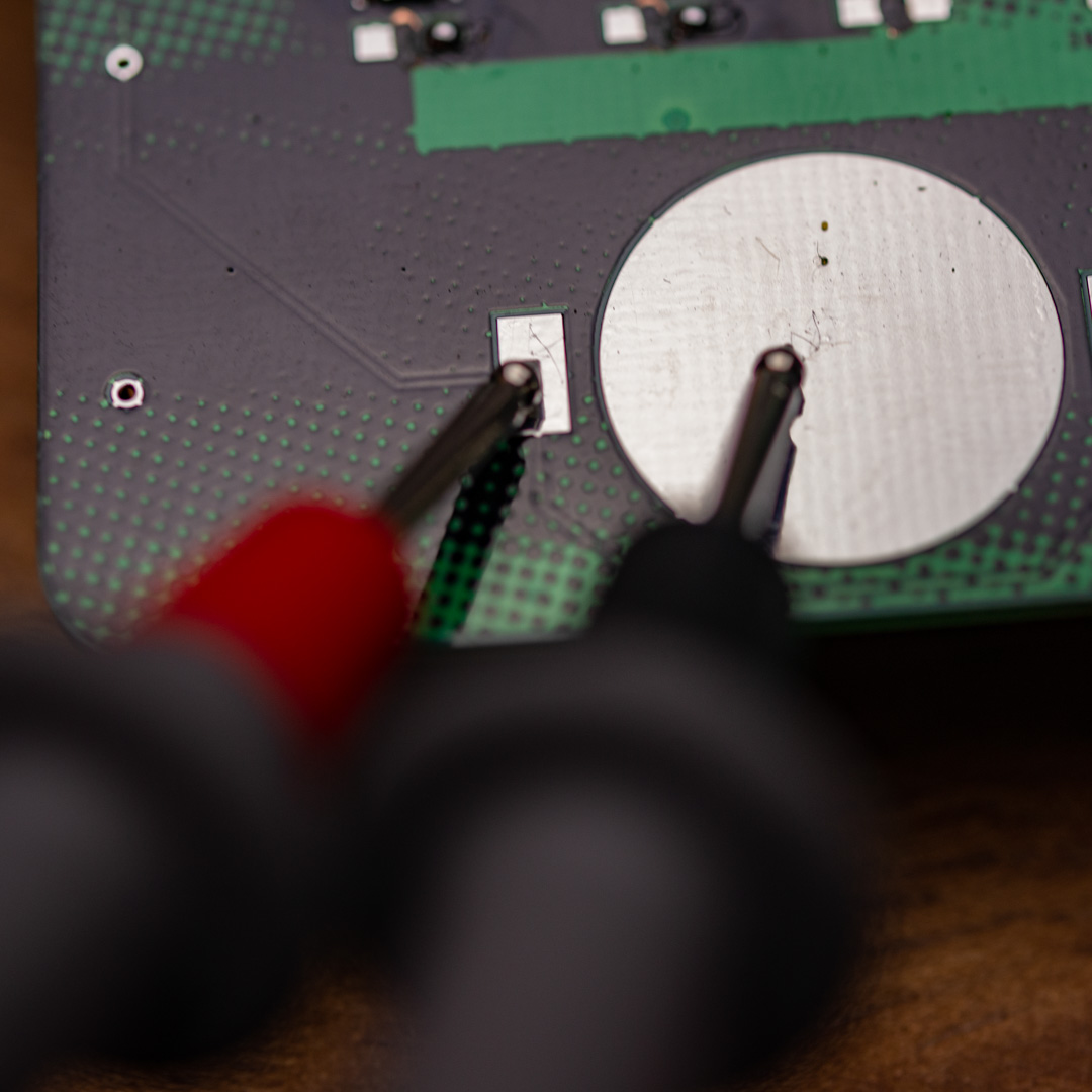
If you check regularly and find a short circuit, you know that it’s likely related to the last solder joint you just made and you don’t have to rework the whole board to locate the problem.
Deciding what to put on
If you just want something to light up and only have very little experience soldering SMD components, you can decide to only put in the flip-flop circuit, power switch and battery holder. Those components are not too difficult, and you will likely not have trouble with short circuits, since the distances are fairly large around those components.
If you want to have the glowing blue and green lights, you will likely need to spend a total of 2-3 hours, unless you are somewhat experienced in handsoldering SMD components, in which case you can probably complete the whole thing in under an hour.
If yor are planning on putting on the backlight later on, remember not to put in the battery holder flush with the PCB, because then the leads won’t be long enough, when you have to put it back on after mounting the LEDs and resistors behind the 35c3 logo, since those sit under the battery holder.
Overview of components
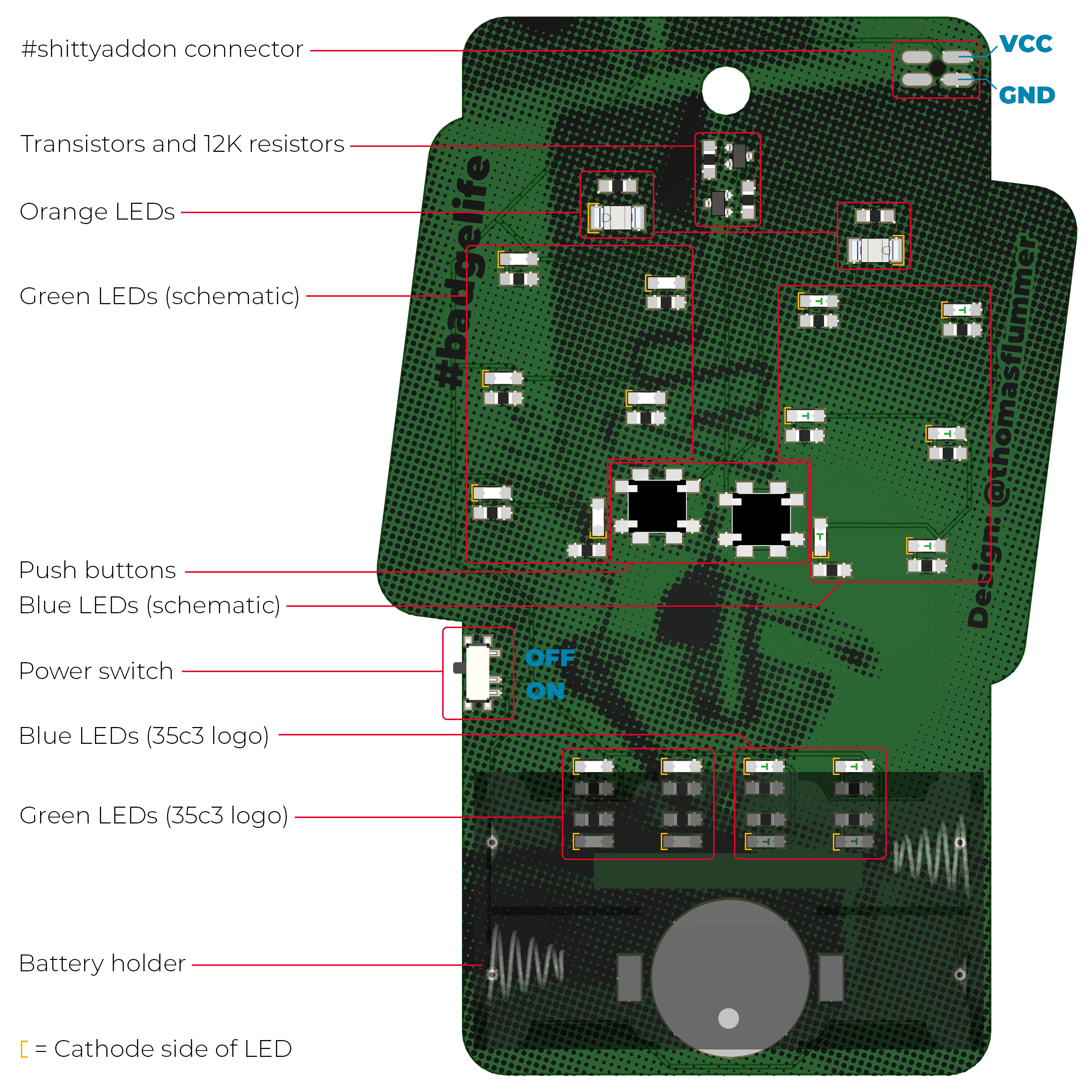
Below is an overview of where all the components go on the PCB, and for the LEDs, there is also a marking on where the cathode side of the component must be. There are more details about how to determine the cathode side of the components further down in this guide. If you are on a small screen (eg. a mobile phone) it is recommended to zoom in a bit on this drawing, for details like the cathode markings, etc.
Flip-flop circuit
The flip flop circuit should go on fairly easy, the components are more or less normal and only very little rework has been done around these parts, so the risk of short circuits is relatively low with these parts.
Power switch
The power switch has two small dimples, that matches the two holes in the PCB, so it is fairly easy to align, but you will need to hold it with your tweezers, otherwise it will follow the soldering iron, when you remove it on the first solder joint.
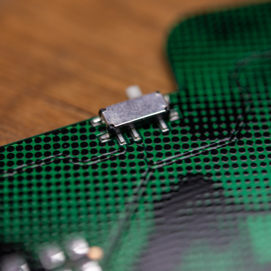
After putting it in place, heat up the first pin and apply a little bit of solder, remove the soldering iron and check that the switch is still correctly aligned with the footprint. If you have only soldered one pin, it’s easy to heat it up again and move it, but when you have soldered up all the pins, it’s very difficult, since all the pins needs to be heated simultaneously.
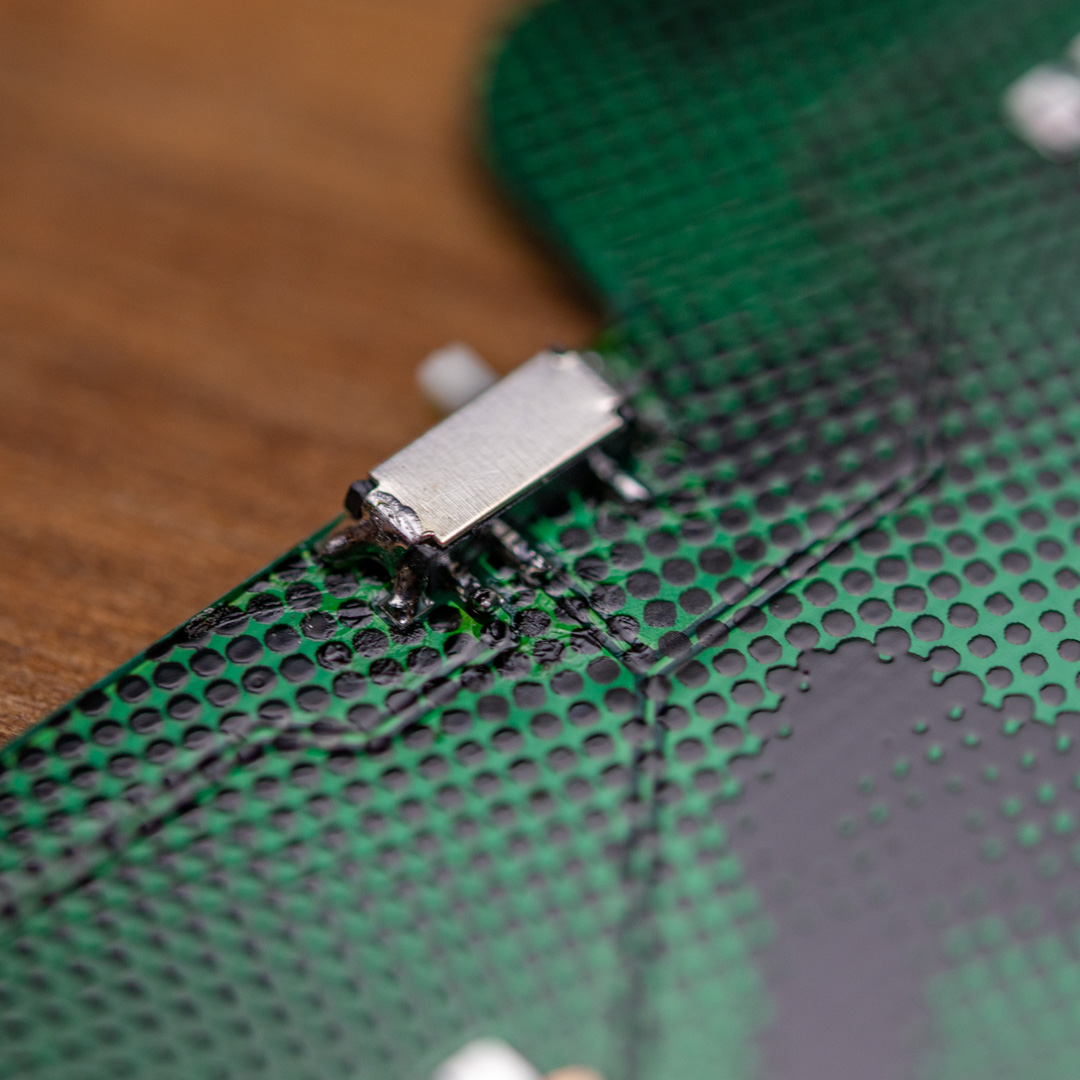
When it’s fully soldered, you turn it on by sliding the switch down towards the battery holder. This is usefull when testing for shorts as mentioned above.
Buttons
The two push buttons need to be slightly modified, because they need to go on up side down on this PCB and in effect be mounted reverse. These buttons are NOT designed for this, so you will need to bend the pins back as illustrated in the image below. The left one has had the pins bent back, the one on the right is how it comes in the kit.
You can use a small plier, a flat head screwdriver or maybe the flat side of your fingernail, the pins are fairly soft, just be carefull, they will break if you bend them back and forth.
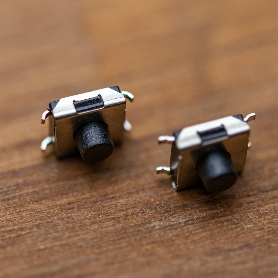
When you want to solder them, it might help to put some of the other componets (in the plastic packaging) under the PCB, to allow the buttons to stick out a little on the other side and lay flat on the top of the PCB.
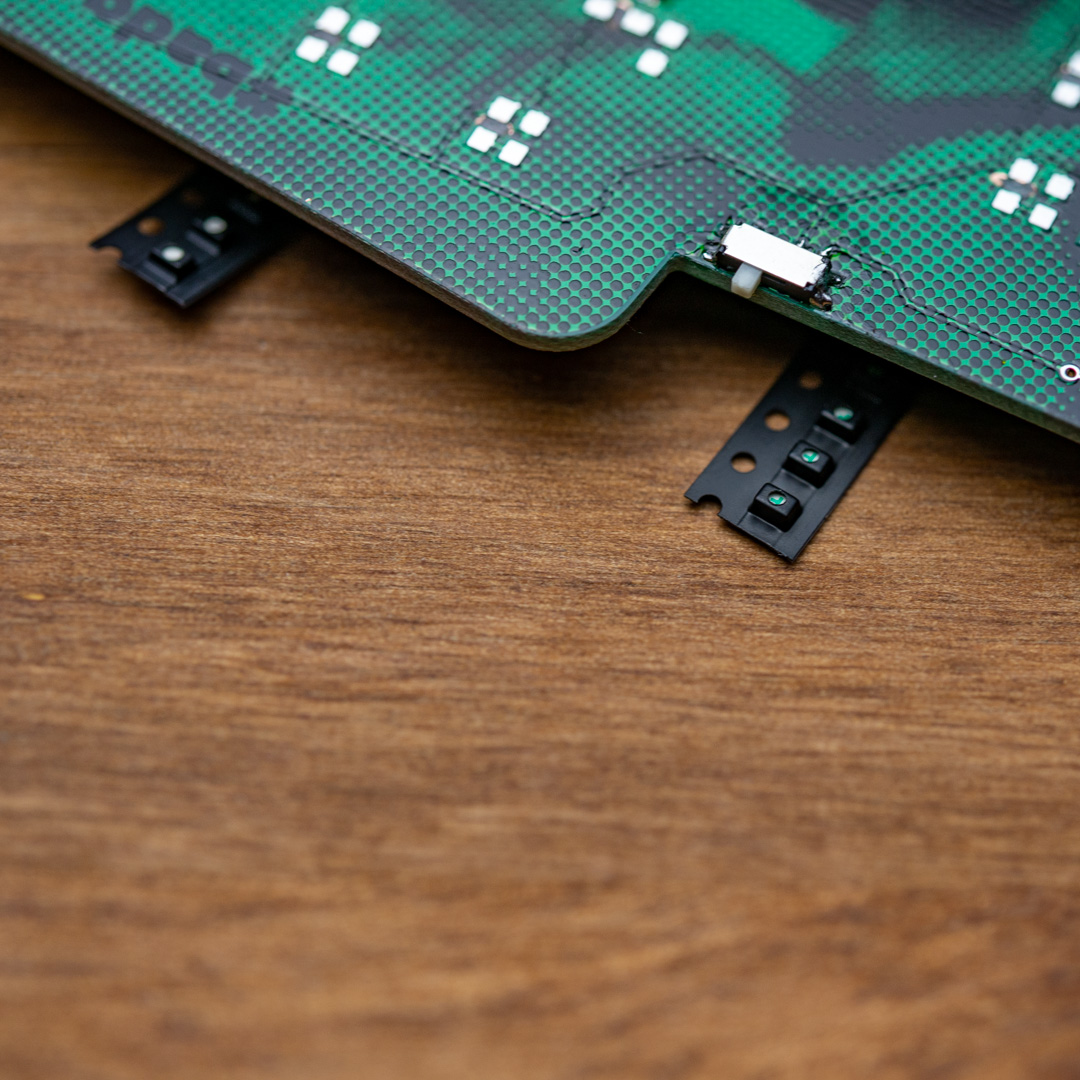
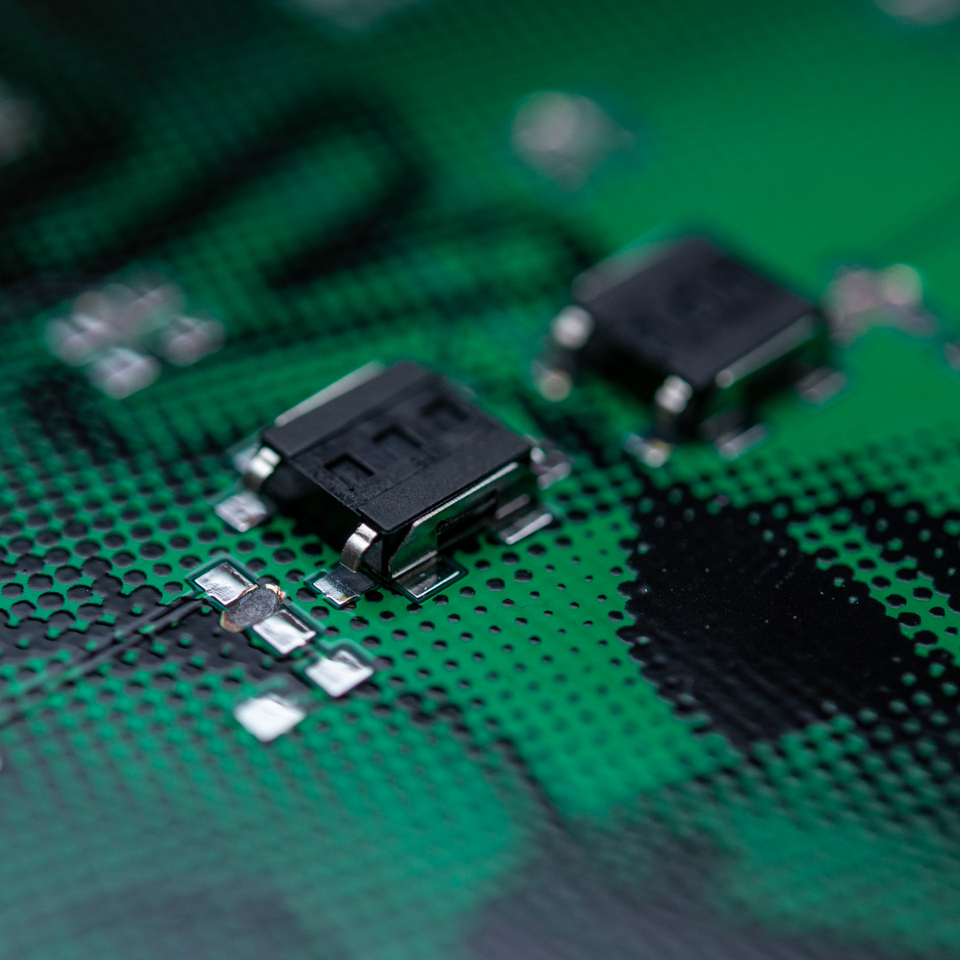
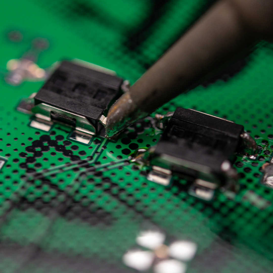
Start by only soldering on one pin and check alignment before continuing on to the other 3 pins. There is no need to solder on the housing, since it’s almost impossible to get the solder to stick on the metal housing on the buttons, so simply ignore those pads.
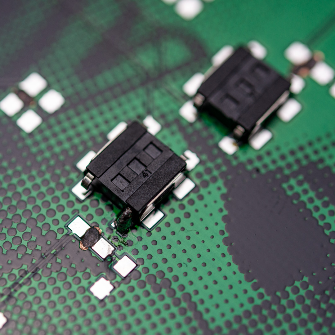
You need a little bit more solder than normal, since it will need to jump a little gap. When heating up, make sure to heat up both the pad and the pin to ease the soldering process.
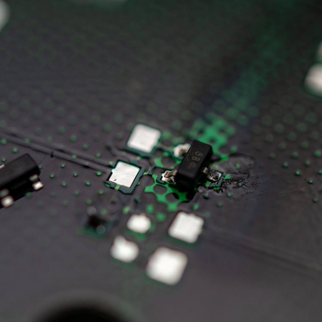
Transistors
The transistors are regular BC817 NPN transistors and this is mounted as it’s designed to be mounted. Put on a tiny solder blob on one of the pads, hold the transistor with your tweezers and push it into place while heating up the small solderblob.
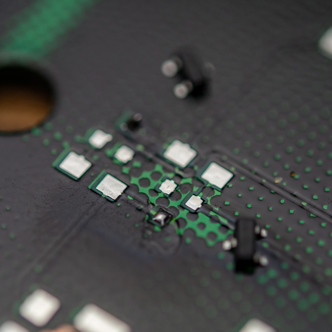
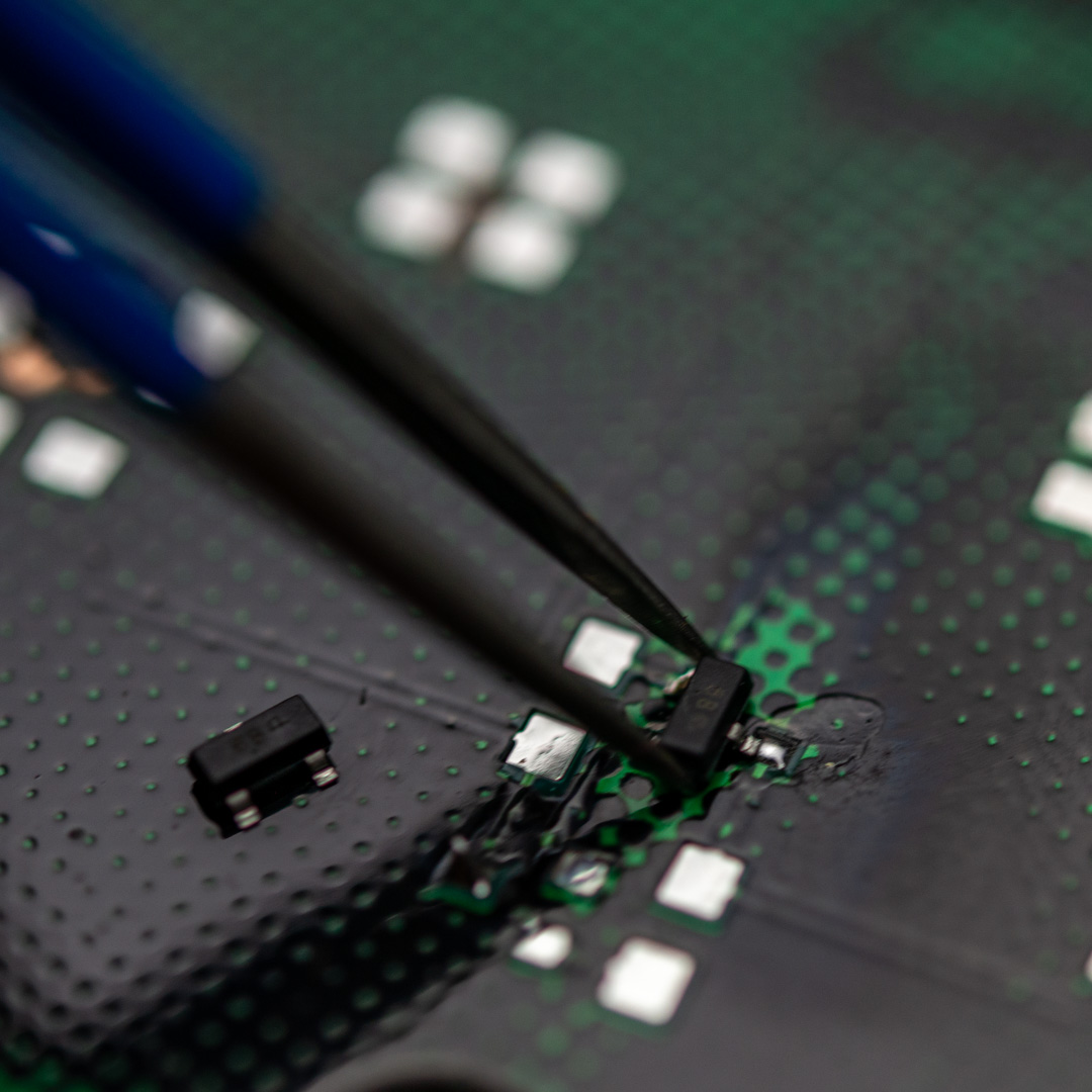
When correctly aligned, solder the two other pins. Very little solder is needed for the connections.
Resistors
There are two types of resistors in this kit. There are two 12K ohm (123 marking on the part) and there is a red marking on the cardboard packaging for those and they need to be mounted on the footprints next to the transistors.
You mount these in the same way, by adding a small solderblob on one pin, holding the part with your tweezers and pushing it into place. When it sits correctly, solder the other side.
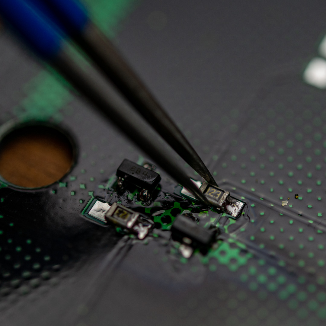
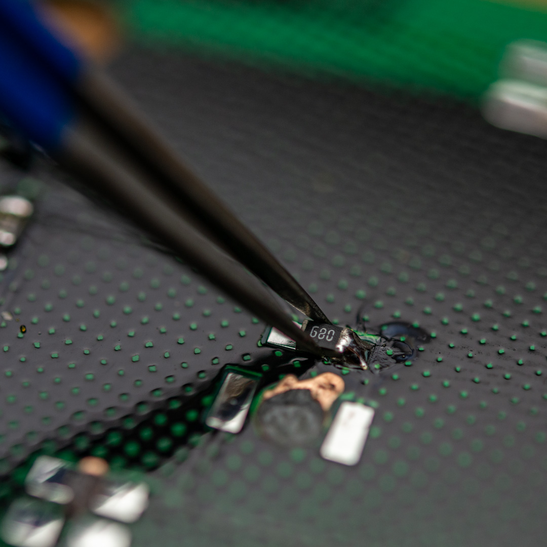
The other resistor in this kit is a 68 ohm (680 marking on the part) and those needs to sit next to each of the LEDs, both the orange, the green and the blue ones. If you are only soldering up the flip flop, you only need to put on the two 68 ohm resistors next to the two larger LEDs (the orange ones).
Orange LEDs
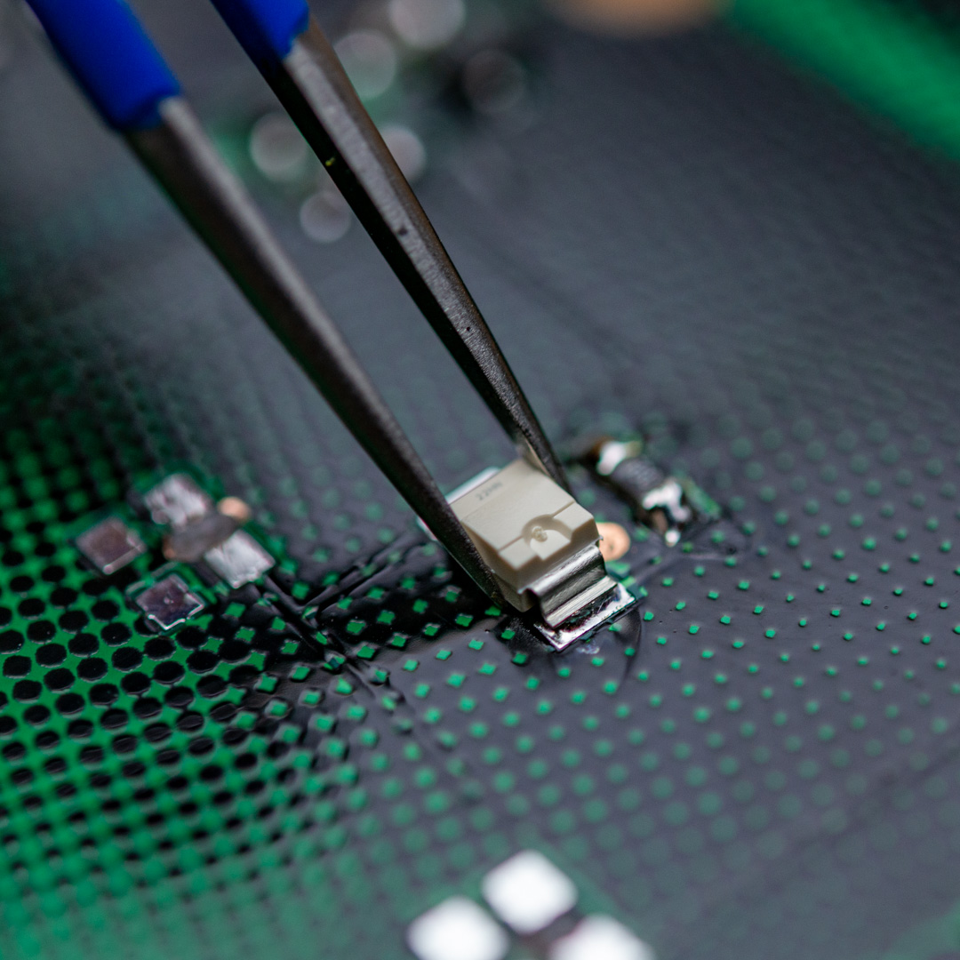
The orange LEDs are the slightly larger ones in a white plastic housing and these are designed to be mounted in this reverse way, so they go on fairly easy, using the same principle as the other parts, but they need to be oriented correctly.
When looking at the back of the board (where the components are) and have the battery holder facing down, the right LED needs to have the little half circle cutout facing to the right as shown on this image:
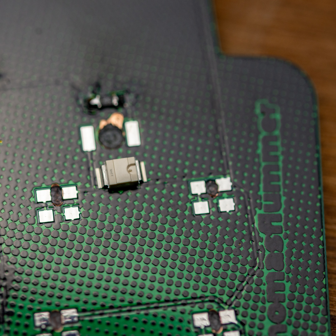
The LED on the left will need to be oriented, with the little notch to the left, as illustrated here:
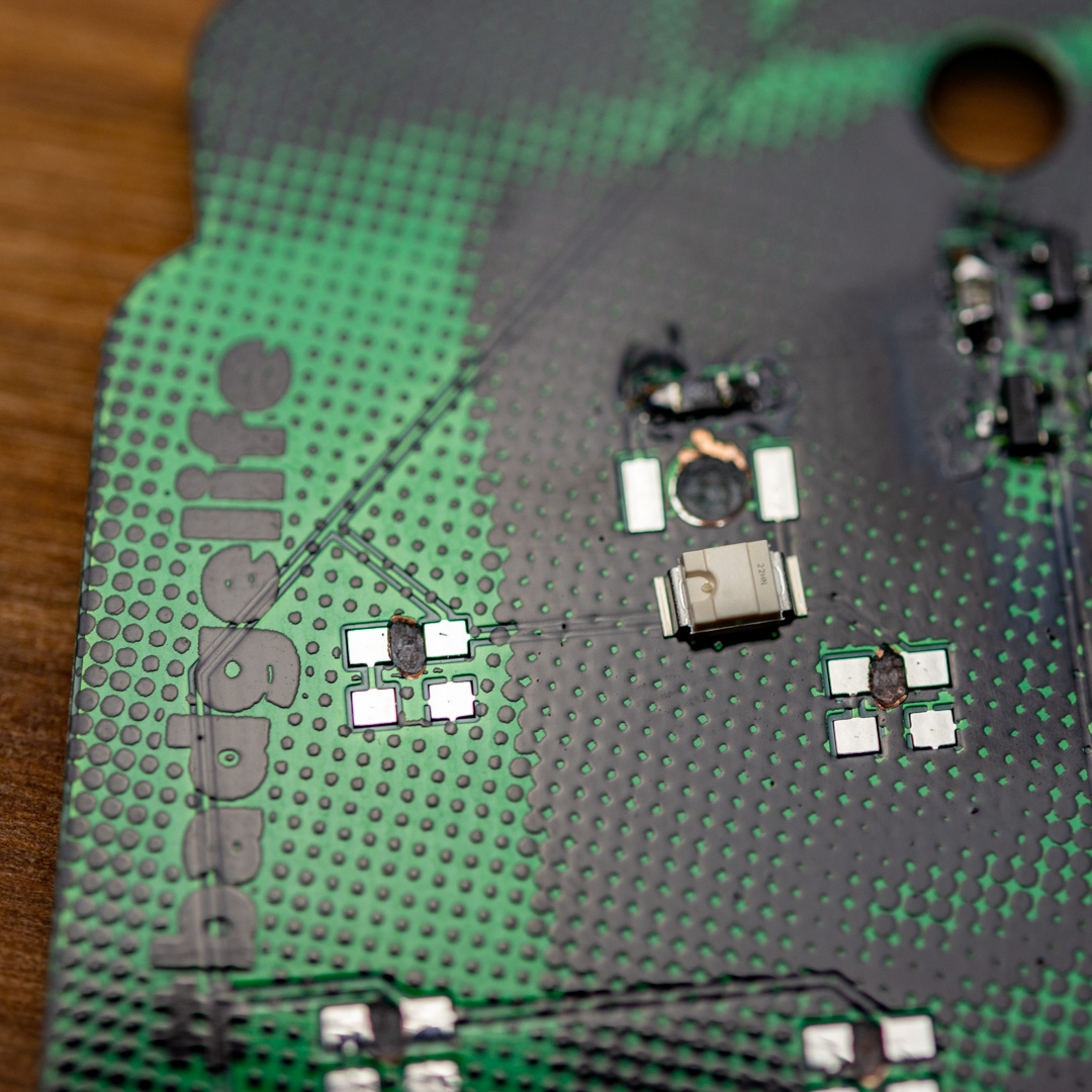
Solder them on like the resistor, holding the LED with your tweezers and soldering one pin at a time.
Test
It’s now time to test it all. If you put in 2 AA batteries in the battery holder, you can put in the battery holder without soldering it, but it’s good enough to test the functionality.
When putting in the battery holder, be careful not to scratch the PCB too much. The pins are a little sharp. The battery holder can go in either way, as long as it’s on the back side.
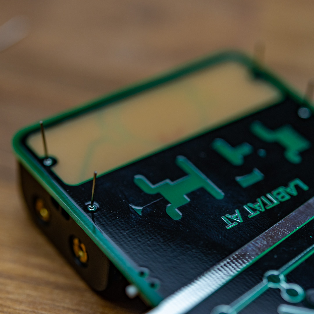
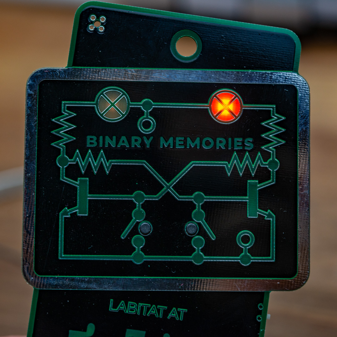
When the battery holder is in and the power swtich is turned on (position down towards the battery holder), one of the orange LEDs should light up.
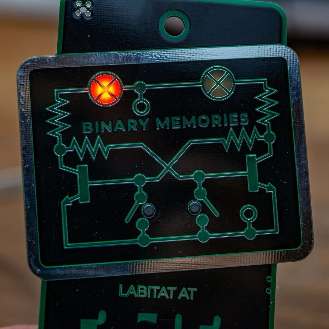
You can now try to push the two buttons, one at a time and see if you can switch which orange LED lights up. When you click the right button, the left LED should light up, and when you click the left button, the right LED will light up.
Backlight glow
The backlight glow is simply a lot of small 0805 SMD leds in blue and green, but they are mounted up side down, which they are NOT designed to be, so you will need to add a little bit more solder than normal to jump the gap.
For each LED, there are also a 68 ohm resistor, that is mounted next to the LED. These are normally called current limiting resistors and prevent the LEDs of burning out.
Resistors
These resistors go on the same way as the others, but it might make sense to prepare a bunch and then solder on the resistors (only the first pin) and then finnish off all the other pins. The resistors will likely go on without too much risk of a short circuit, since there are a good soldermask around these.
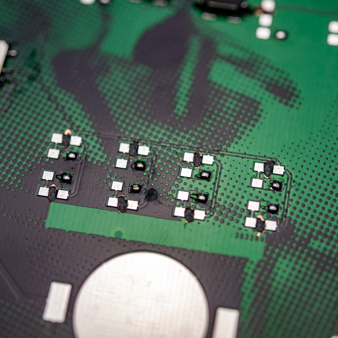
When one pad per resistor is prepped with a small solder blob, it’s time to add in the resistors.
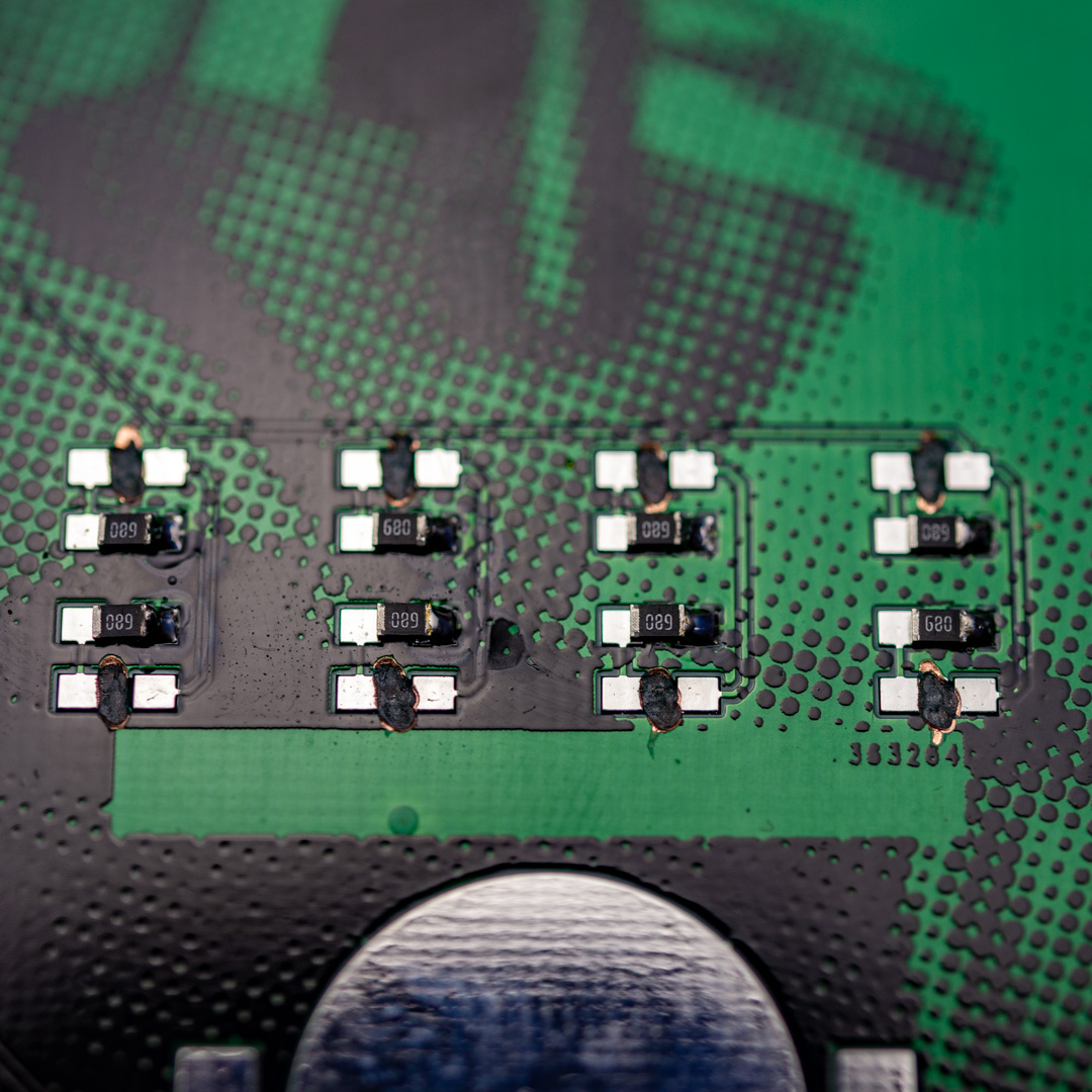
And then solder up the other side of each resistor.
LEDs
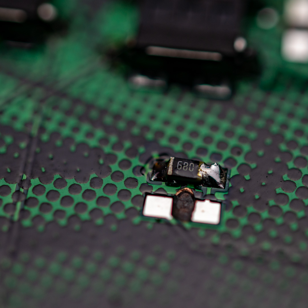
The LEDs are a little more tricky, since they need to go on the right way. It needs to have the cathode connected to the pad, that has a trace to the resistor AND it has to be put up side down, which looks somewhat wrong.
There is of course total freedom as to where you place the LEDs, but to achieve the look og having green on the right and blue on the left you will need to put them on opposite on the back, so on the right side (seen on the back), you will put the blue and on the left side all the green ones.
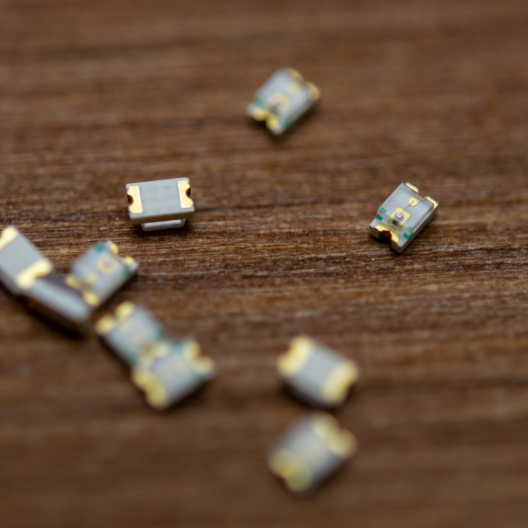
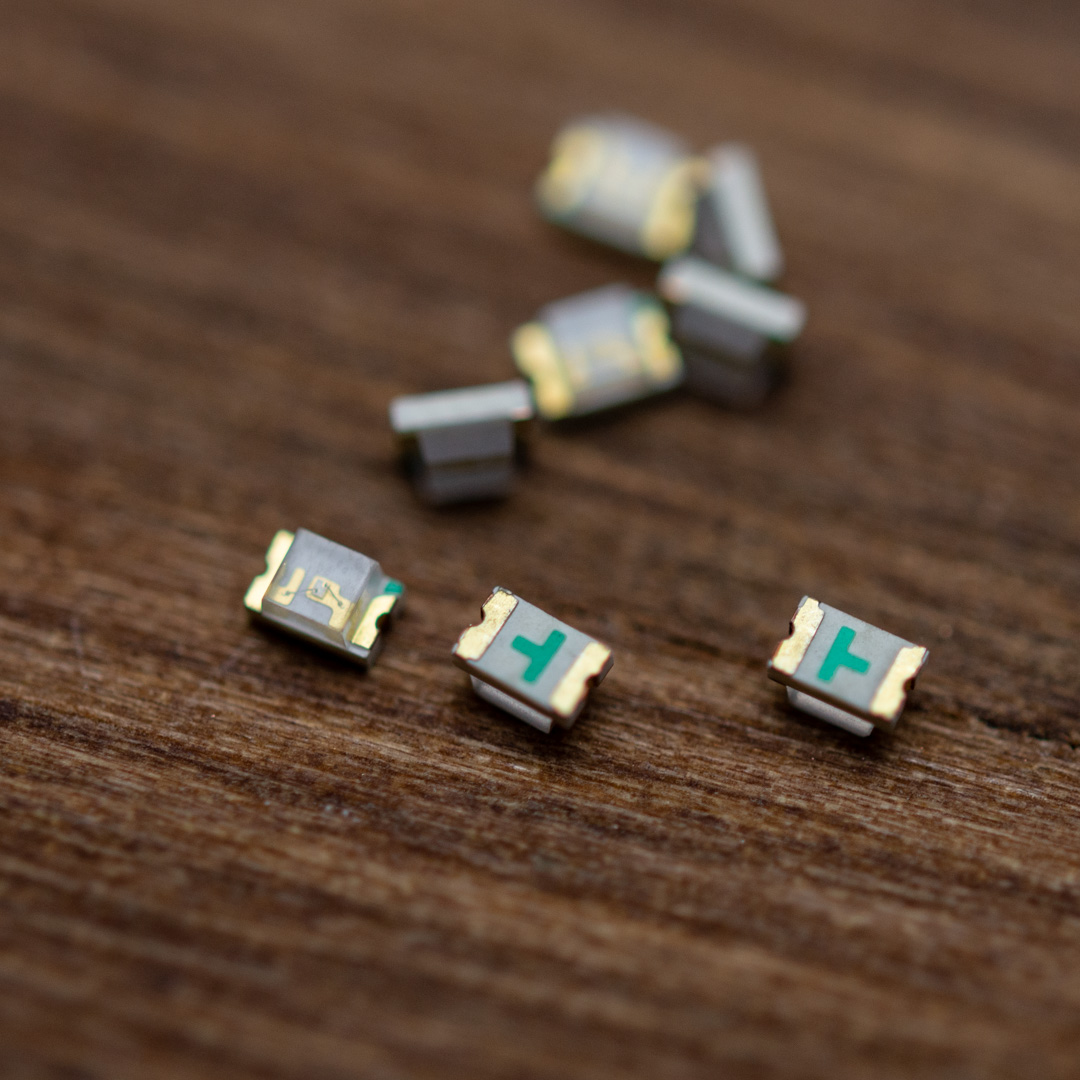
If you look at the LEDs, there are some small green markings near the clear plastic top on one side and that is the marking for the cathode. On the green LEDs, there are no markings on the bottom, so you will have to check the polarity, and then grab the LED with your tweezers without rotating it.
All of these LEDs need to have the cathode pointing to the left, when you look at the back of the board, with the battery holder in the bottom. The only exceptions are the two LEDs closest to the two buttons, they should be positioned with the cathode facing down towards the battery holder.
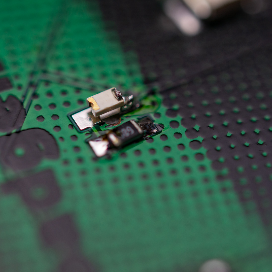
Do it similarly as the other components, by placing a blob of solder on one pad (a little more than the other components, since you need to bridge a gap) and then solder it on holding it with your tweezers.
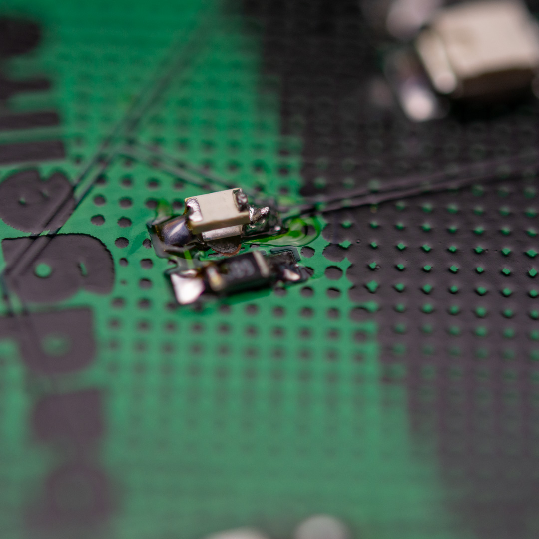
Then finish of the other side of the LED.
You can then test to see if there is a short circuit (as decribed above in the good practices section) and if it all checks out, you can put on the battery pack and test if the LED lights up. It only turns on, when the power switch is in the on position.
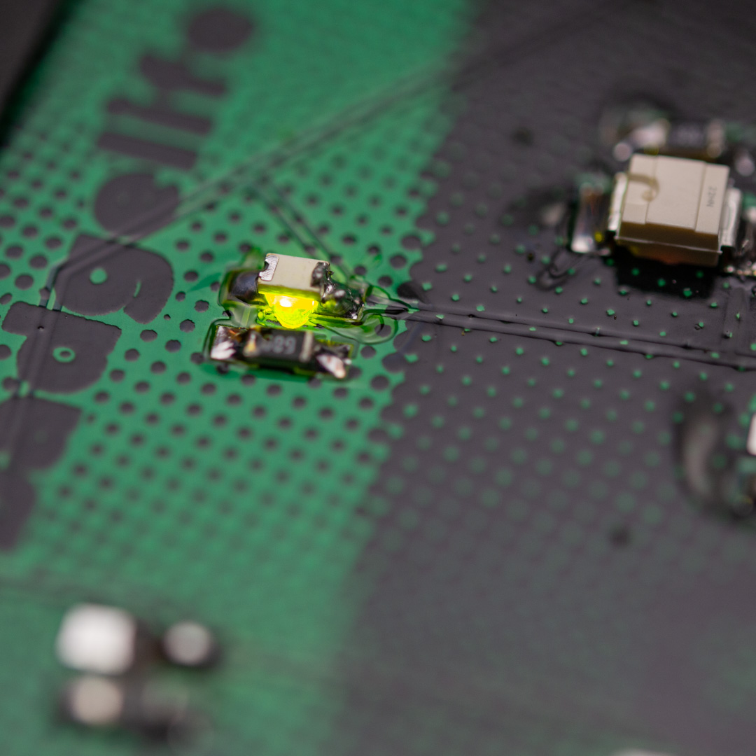
You then need to repeat this for all the green LEDs.
The blue ones are more or less the same, but they also have a T marking on the bottom and the bottom of the T is the cathode.
Battery holder
There is two footprints for battery holders: A 3v coin cell holder and a holder for two AA batteries. Even though it is possible to power the badge from a coin cell, it will not stay lit up for very long and for that reason, only the 2x AA holder is included in the kit.
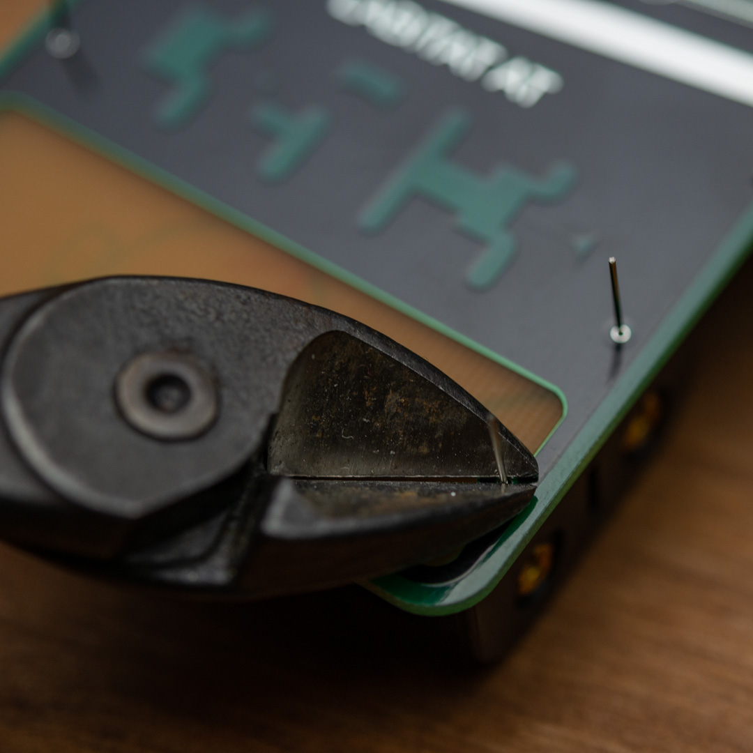
When you have all the other components soldered on, you need to put on the battery holder. Simply feed through the 4 pins and press the holder against the PCB and parts that sit under the holder. While keeping preasure on the holder, cut off the excess leads with a heavy duty side cutter. If you let go of the battery holder, one or more leads might jump out of the hole, and it can be a little tricky to get it mounted again, with the short leads, so try to keep it in place. The only thing left now, is to solder the 4 pins on the front and a tip is to use a little extra solder, and maybe form a little solder ball, so that the joint isn’t pointy and ends up scratching you or your clothes.
#shittyaddon connector
As has been customary for electronic badges this year, there is of course also a place for a #shittyaddon connector on this badge. It is optional to put this connector on, but having it makes it easy to change addons. Where the #shittyaddon standard has pins for an I2C connection, these pins are unconnected on this badge, since there are no microcontroller on the board, so this will in effect be a power only solution.
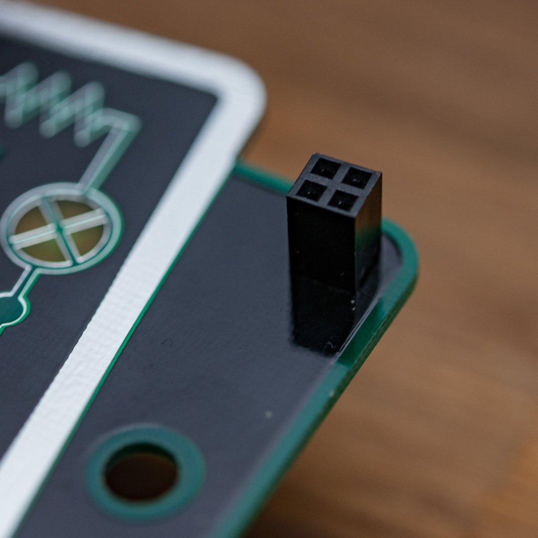
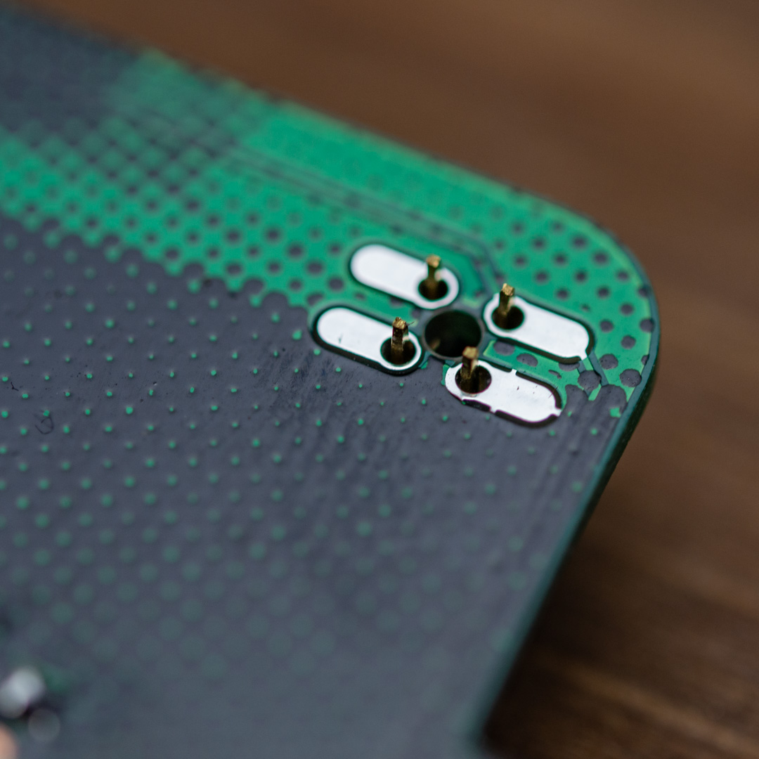
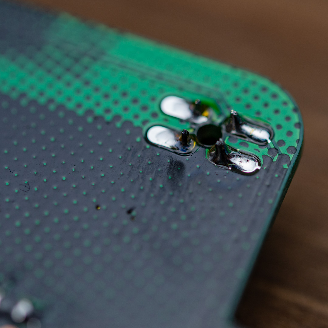
The footprint on this PCB is a dual purpose one and supports a fancy, expensive, low profile, reverse mount female header, but at the same time, also supports regular 2x2 female headers, and it’s the later type that is included in this kit.
To mount it, simply insert the header through the holes, turn the board over holding the header in place and put in on your worksurface, so that the PCB weighes down on the header and keeps everything in place, then solder the 4 pins on the back.
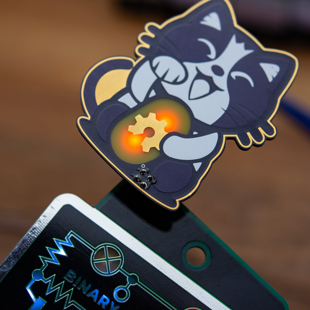
With the connector on, you can easily put on #shittyaddons like the Lucky OSHCat by TwinkleTwinkie
There are no active polarity protection, and for esthetic reasons, there are no markings on the PCB, but the connector roughly follows the standard, when it comes to orientation, and is correct for having an addon sitting upright. Seen from the front of the badge, the upper left pin is VCC and the lower left is GND, the other two pins are unconnected.
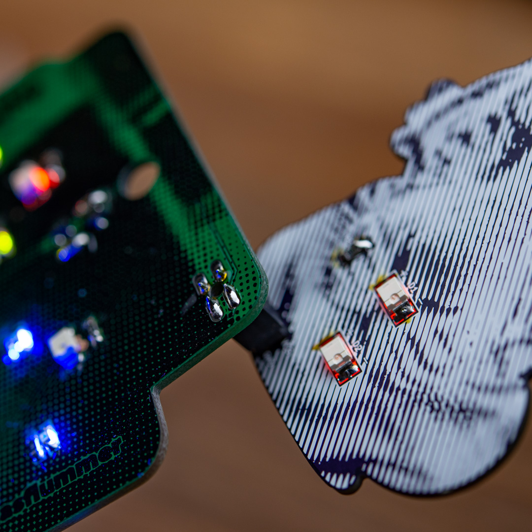
If you have the fancy, expensive header, you can use a 2x2 male pinheader to hold it in place, while you solder it on like all the other SMD components.
Power to the #shittyaddon connector is also disconnected, when you flip the power switch to turn off the badge.
Locating a short circuit
On this board, the most likely short circuit will be between VCC and the ground plane, and they will most likely be due to the fact that the groundplane is exposed arond the LEDs, where I have milled away some copper to allow the LEDs to shine through the PCB due to a design mistake.
When there is enough flux, the solder will flow and try to stay within the pads on the PCB, but if you heat up the same solder over and over, the flux that is in the solder on the roll, is burned away, and the solder doesn’t flow as nicely, and the risk of having the solder spread out a bit and maybe also touch the exposed ground plane is higher.
A visual inspection is often enough to find problemetic places, though you might need a magnifying glass or if awailable, a microscope.
If you encounter a short circuit between VCC and ground, you should check the solderings that you did since the last test without a short. You can try to heat up the solder joints again, maybe adding a bit of extra solder, cleaning your iron and then go back to the solder joint and that way removing a little bit of solder. If you have too much solder on the joint, you can also use solderwick to suck up some of that solder. Be very carefull with the solder sucktion tools, since these components are fairly small and the tools are usually fairly big and clumsy, solderwick will likely be easier to work with.
If you have some flux, adding a little bit and heating up a solder joint might also help.
Fixing errors
All PCBs have been measured for continuity before being packed, so there should not be any disconnected traces, but I made a mistake on my demo PCB and had to do a little fix. This is very thin wirewrap wire, that is simply soldered on the the two pads, to replace the PCB trace, that was accidentally cut during rework. In the electronics industry, this is often refered to as a blue wire fix.
